


| Orientasi: | Vertikal |
| Instalasi: | Lantai Mounted |
| Persyaratan Ruang: | 7 sq.ft. |
| Sertifikasi: | Bagian VIII ASME |
| Shell Bahan: | Besi cor |
| Shell Penilaian | |
| 75 psi @ 350 o F 50 psi @ 300 o F |
| Coil Penilaian | |
| 200 psi @ 350 o F 200 psi @ 300 o F |
| Coil Bahan: | Tabung Tembaga SB75 |
| Coil Ukuran | |
| 0,5 "OD 18 BWG 0,625 "OD 18 BWG |
| Tekanan Drop: | Pemanas air InstaFlow dirancang dengan penurunan tekanan air dihitung sekitar 8 psig antara pasokan air dingin dan air panas outlet. |
| Air Suhu Ideal Jangkauan Pengoperasian: | 105-185 o F |
| Perangkap Kondensat Utama: | F & T Jenis |
| Drip Perangkap: | Termostatik Jenis |
| Uap Tekanan Gauge: | 30 "Hg - 30 psig |
| Air Gauge: | 70-270 o F, 0-200 psi 20-120 o C, 0-1400 kPa |
| Frame: | Baja Besi Sudut |
| Pelindung Kain Kafan: | 20GA Baja Galvanis |
| Isolasi: | 2-lb. Kepadatan Fiberglass |
| Jaminan | |
| 10 Tahun 10 Tahun |
| Berat Pengiriman (lbs.): | |
| 320 405 450 615 |
Jumat, 02 September 2011
1 Spesifikasi Model Water Heater F
0 Large Steam System Condensers
Heat Exchanger Knowledge | Heat Exchanger Companies Suppliers
Since the condensation takes place, the latent heat of condensation term used instead of latent heat of vaporization. Latent heat of condensation of steam is passed into the water flowing through the condenser tubes.
After the steam condenses, saturated liquid continues to transfer heat to the cooling water as it falls to the bottom of the condenser, or hotwell. This is called subcooling, and a certain amount desired. A few degrees subcooling prevents condensate pump cavitation. The difference between the saturation temperature for an existing vacuum condenser and the condensate temperature is called condensate depression. This is expressed as the number of degrees of depression or degrees subcooled condensate. Excessive condensate depression decreases the efficiency of plant operations due to subcooled condensate must be heated in a boiler, which in turn requires more heat from the reactor, fossil fuels, or other heat sources.
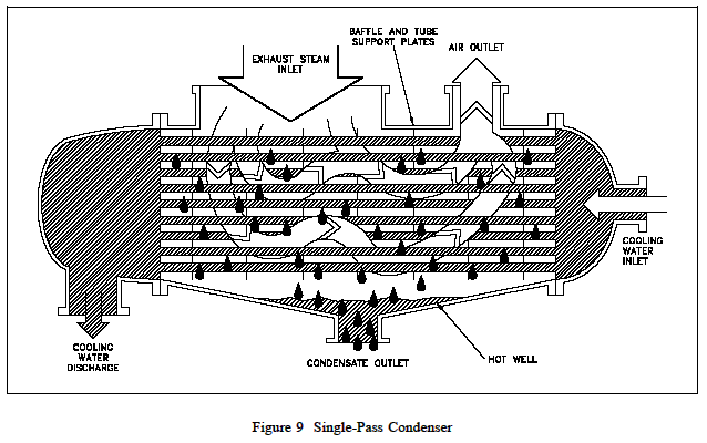
Non-condensable gas is also blanket the condenser tubes, thereby reducing the heat transfer surface area of the condenser. This surface area can also be reduced if the level of condensate is allowed to rise above the lower tube of the condenser. Decrease the heat transfer surface has the same effect as reducing the flow of cooling water. If the condenser operating near design capacity, a reduction in the effective surface area results in difficulty maintaining condenser vacuum.
Temperature and flow rate through the condenser cooling water temperature control of the condensate. This in turn controls the saturation pressure (vacuum) of the condenser. To prevent condensate from rising to levels below the condenser tube, hotwell level control system can be used. Varying the current from the condensate pump is one of the methods used to improve control hotwell level. A level sensing network controls the condensate pump speed or pump discharge flow control valve position. Another method uses overflow system that spills water from hotwell when high level is reached.
Vacuum the condenser must be maintained as close to 29 inches Hg practical. This allows maximum expansion of steam, and therefore, to work optimally. If the condenser is perfectly air-tight (no air or noncondensable gases present in the exhaust steam), will be necessary only to condense the steam and remove the condensate to create and maintain a vacuum. Sudden drop in the volume of vapor, like condenses, will maintain the vacuum. Pumping water from the condenser as fast as formed will maintain the vacuum. However, it is impossible to prevent the entry of air and other noncondensable gases into the condenser. In addition, there must be some method to initially cause a vacuum in the condenser. This requires the use of an air ejector or vacuum pump to establish and help maintain condenser vacuum.
Basically jet air ejector pumps or eductors, as illustrated in Figure 10 below. In operation, a jet pump has two types of liquids. They are high pressure fluid flowing through the nozzle, and fluid being pumped which flows around the nozzle into the diffuser throat. High-speed fluid into a diffuser where the molecules that attack other molecules. These molecules in turn carried away by high speed liquid out of the diffuser creating a low pressure area around the mouth of the nozzle. This process is called entrainment. Lowpressure area will draw more fluid from the nozzle into the diffuser throat. As the fluid moves down the diffuser, the increasing speed of converting back to the pressure. The use of steam at a pressure between 200 psi and 300 psi for high pressure fluid enables singlestage air ejector to draw about 26 inches Hg vacuum.

A vacuum pump may be all kinds of motor-driven air compressor. Suction is attached to the condenser, and the release into the atmosphere. A common type uses rotating vanes in the housing ellipse. Single-stage, rotary-vane units are used for vacuums to 28 inches Hg. Two stage units can draw vacuums to 29.7 inches Hg. Vacuum pumps have the advantage over air ejector in that it requires no source of steam for the operation. They are usually used as the initial source of vacuum for condenser start-ups.
Senin, 29 Agustus 2011
2 Parts and How it Works plant: Boiler

PLTU Paiton, Jawa Timur
Steam Power (power plant) consists of several major systems, ie:
1. Turbine & Generator
2. Boiler (Steam Generator)
3. Coal Handling System
4. Ash Handling System
5. Flue Gas System
6. Balance of Plant
Turbine & generator can be regarded as the heart of the plant, because of the electrical energy is generated. Generator which rotates with constant speed, generating electrical energy supplied to the network interconnection and then distributed to consumers.
Steam turbine (steam turbine) which serves to turn a generator, consisting of HP (high-pressure) turbine, IP (intermediate-pressure) turbine and LP (low-pressure) turbine.
Turbine & generator has some supporting equipment, the lubricating oil system and the generator cooling system.
Boiler (steam generator) function to convert water into steam. Very high-pressure steam produced by boilers used to rotate the turbine. Boiler is divided into several sub-systems, namely:
- Boiler steel structure house
- Pressure parts
- Coal system
- Water system
- Boiler Cleaning System

Boiler (Steam Generator)
As the name implies, the boiler house structure is steel building steel frame structure, in which all equipment installed steam generator. This steel frame building height between 50 m (plant capacity of 65 MW) to 100 m (600 MW capacity power plant).
Pressure part system is a major part of the steam generator. These sections serve to convert water into high pressure steam (superheated steam) at temperatures between 500-600 degrees C.
Water supplied to the boiler, first came into the economizer inlet header, continue to be distributed to the economizer elements, reconvening in eco outlet header and then piped into the steam drum. Backpass economizer is located in the area (at the back of the boiler house), while the steam drum at the front of the roof area.
Named economizer as part of this serves to raise the temperature of incoming water boiler by utilizing exhaust gases from the combustion of coal in the furnace area (combustion chamber). By preheating the boiler economizer this efficiency can be improved.
Due to heating by convection in the furnace and due to gravity, water in the steam drum water circulation had dropped to the lower water wall headers via pipe downcomers. From the lower waterwall headers again experienced water circulation by heat, water rises toward the upper wall-tube headers via the tube water wall panels. Then from the upper waterwall header restored water to the steam drum through riser pipes.
So the result of coal burning hot water undergoes a continuous circulation. This circulation causes the water in a water wall panels & steam drum partially transformed into steam.
In a large-capacity power plant, boiler circulation is assisted by water circulating pump mounted on the bottom of the pipe downcomers. Faster circulation will cause the speed of the water changes into steam are also greater.
Inside there is a steam separator drum which serves to separate the steam from the water. The steam is separated, from the steam drum steam is channeled to the roof inlet header connected to the boiler roof panel. Boiler roof panel that carries the steam back into backpass panel.
of backpass panels, steam is channeled into the Low Temperature superheater (LTS) that is in backpass area, above the economizer elements. of LTS steam superheaters channeled into Intermediate Temperature (ITS). Next through the superheater pipe-desuperheater, steam superheater was taken to High Temperature (HTS) elements to undergo the final heating process becomes superheated steam.
ITS and HTS elements located inside the furnace (coal combustion chamber) the top. Some boiler manufacturers give different names to the LT, IT and HT superheater.
Of High Temperature superheater outlet headers, superheated steam with temperatures of 500-600 degrees C and very high pressure to the steam turbine channeled through the main steam pipe.
In the small-capacity power plant, the steam goes to the High Pressure Turbine, continues to Low Pressure Turbine and out into the condenser. While the large-capacity power plant, after turning the HP turbine steam is brought back to the boiler through the cold reheat piping.
Inside the boiler the steam to warm up again in Reheater elements. Reheater elements are usually located between the furnace area and backpass area.
After having re-heating, steam reheated to Intermediate Pressure Turbine channeled through pipes Hot reheat. After turning Intermediate and Low Pressure Turbine, a new steam out into the condenser.
0 How it Works Boiler
Heat energy generated in the boiler system has a value of pressure, temperature, and flow rates that determine the use of steam to be used. Based on all three systems recognize circumstances boiler pressure low-temperature (low pressure / LP), and pressure-high temperature (high pressure / HP), with the difference that the utilization of the steam out of boiler systems used in a process to heat your fluid and run a machine (commercial and industrial boilers), or generating electrical energy by converting heat energy into mechanical energy and then turn a generator to produce electrical energy (power boilers). However, there are also combining the two boiler systems, which use pressure-high temperature to generate electrical energy, then the remaining steam from the turbine with low pressure-temperature conditions can be utilized in industrial processes with the help of a heat recovery boiler.
The system consists of boiler feed water systems, steam systems, and fuel system. Water system provides water to the boiler automatically as needed steam. Various valves are provided for purposes of maintenance and repair of the system feed water, feed water treatment is required as a form of maintenance to prevent damage from the steam system. Steam system collects and controls the production of steam in the boiler. Steam is directed through a piping system to the user's point. The entire system, steam pressure is set using the faucets and monitored with a pressure monitor. The fuel system is all the equipment used to provide fuel to generate the necessary heat. Equipment required on the fuel system depends on the type of fuel used on the system.
The system consists of boiler feed water systems, steam systems, and fuel system. Water system provides water to the boiler automatically as needed steam. Various valves are provided for purposes of maintenance and repair of the system feed water, feed water treatment is required as a form of maintenance to prevent damage from the steam system. Steam system collects and controls the production of steam in the boiler. Steam is directed through a piping system to the user's point. The entire system, steam pressure is set using the faucets and monitored with a pressure monitor. The fuel system is all the equipment used to provide fuel to generate the necessary heat. Equipment required on the fuel system depends on the type of fuel used on the system.
Minggu, 28 Agustus 2011
2 Siklus PLTU Pembangkit Listrik Tenaga Uap
Sebuah pembangkit listrik jika dilihat dari bahan baku untuk memproduksinya, maka Pembangkit Listrik Tenaga Uap bisa dikatakan pembangkit yang berbahan baku Air. Kenapa tidak UAP? Uap disini hanya sebagai tenaga pemutar turbin, sementara untuk menghasilkan uap dalam jumlah tertentu diperlukan air. Menariknya didalam PLTU terdapat proses yang terus menerus berlangsung dan berulang-ulang. Prosesnya antara air menjadi uap kemudian uap kembali menjadi air dan seterusnya. Proses inilah yang dimaksud dengan Siklus PLTU.
Air yang digunakan dalam siklus PLTU ini disebut Air Demin (Demineralized), yakni air yang mempunyai kadar conductivity (kemampuan untuk menghantarkan listrik) sebesar 0.2 us (mikro siemen). Sebagai perbandingan air mineral yang kita minum sehari-hari mempunyai kadar conductivity sekitar 100 – 200 us. Untuk mendapatkan air demin ini, setiap unit PLTU biasanya dilengkapi dengan Desalination Plant dan Demineralization Plant yang berfungsi untuk memproduksi air demin ini.
Secara sederhana bagaimana siklus PLTU itu bisa dilihat ketika proses memasak air. Mula-mula air ditampung dalam tempat memasak dan kemudian diberi panas dari sumbu api yang menyala dibawahnya. Akibat pembakaran menimbulkan air terus mengalami kenaikan suhu sampai pada batas titik didihnya. Karena pembakaran terus berlanjut maka air yang dimasak melampaui titik didihnya sampai timbul uap panas. Uap ini lah yang digunakan untuk memutar turbin dan generator yang nantinya akan menghasilkan energi listrik.
Secara sederhana, siklus PLTU digambarkan sebagai berikut :

Siklus PLTU
- Pertama-tama air demin ini berada disebuah tempat bernama Hotwell.
- Dari Hotwell, air mengalir menuju Condensate Pump untuk kemudian dipompakan menuju LP Heater (Low Pressure Heater) yang pungsinya untuk menghangatkan tahap pertama. Lokasi hotwell dan condensate pump terletak di lantai paling dasar dari pembangkit atau biasa disebut Ground Floor. Selanjutnya air mengalir masuk ke Deaerator.
- Di dearator air akan mengalami proses pelepasan ion-ion mineral yang masih tersisa di air dan tidak diperlukan seperti Oksigen dan lainnya. Bisa pula dikatakan deaerator memiliki pungsi untuk menghilangkan buble/balon yang biasa terdapat pada permukaan air. Agar proses pelepasan ini berlangsung sempurna, suhu air harus memenuhi suhu yang disyaratkan. Oleh karena itulah selama perjalanan menuju Dearator, air mengalamai beberapa proses pemanasan oleh peralatan yang disebut LP Heater. Letak dearator berada di lantai atas (tetapi bukan yang paling atas). Sebagai ilustrasi di PLTU Muara Karang unit 4, dearator terletak di lantai 5 dari 7 lantai yang ada.
- Dari dearator, air turun kembali ke Ground Floor. Sesampainya di Ground Floor, air langsung dipompakan oleh Boiler Feed Pump/BFP (Pompa air pengisi) menuju Boiler atau tempat “memasak” air. Bisa dibayangkan Boiler ini seperti drum, tetapi drum berukuran raksasa. Air yang dipompakan ini adalah air yang bertekanan tinggi, karena itu syarat agar uap yang dihasilkan juga bertekanan tinggi. Karena itulah konstruksi PLTU membuat dearator berada di lantai atas dan BFP berada di lantai dasar. Karena dengan meluncurnya air dari ketinggian membuat air menjadi bertekanan tinggi.
- Sebelum masuk ke Boiler untuk “direbus”, lagi-lagi air mengalami beberapa proses pemanasan di HP Heater (High Pressure Heater). Setelah itu barulah air masuk boiler yang letaknya berada dilantai atas.
- Didalam Boiler inilah terjadi proses memasak air untuk menghasilkan uap. Proses ini memerlukan api yang pada umumnya menggunakan batubara sebagai bahan dasar pembakaran dengan dibantu oleh udara dari FD Fan (Force Draft Fan) dan pelumas yang berasal dari Fuel Oil tank.
- Bahan bakar dipompakan kedalam boiler melalui Fuel oil Pump. Bahan bakar PLTU bermacam-macam. Ada yang menggunakan minyak, minyak dan gas atau istilahnya dual firing dan batubara.
- Sedangkan udara diproduksi oleh Force Draft Fan (FD Fan). FD Fan mengambil udara luar untuk membantu proses pembakaran di boiler. Dalam perjalananya menuju boiler, udara tersebut dinaikkan suhunya oleh air heater (pemanas udara) agar proses pembakaran bisa terjadi di boiler.
- Kembali ke siklus air. Setelah terjadi pembakaran, air mulai berubah wujud menjadi uap. Namun uap hasil pembakaran ini belum layak untuk memutar turbin, karena masih berupa uap jenuh atau uap yang masih mengandung kadar air. Kadar air ini berbahaya bagi turbin, karena dengan putaran hingga 3000 rpm, setitik air sanggup untuk membuat sudu-sudu turbin menjadi terkikis.
- Untuk menghilangkan kadar air itu, uap jenuh tersebut di keringkan di super heater sehingga uap yang dihasilkan menjadi uap kering. Uap kering ini yang digunakan untuk memutar turbin.
- Ketika Turbin berhasil berputar berputar maka secara otomastis generator akan berputar, karena antara turbin dan generator berada pada satu poros. Generator inilah yang menghasilkan energi listrik.
- Pada generator terdapat medan magnet raksasa. Perputaran generator menghasilkan beda potensial pada magnet tersebut. Beda potensial inilah cikal bakal energi listrik.
- Energi listrik itu dikirimkan ke trafo untuk dirubah tegangannya dan kemudian disalurkan melalui saluran transmisi PLN.
- Uap kering yang digunakan untuk memutar turbin akan turun kembali ke lantai dasar. Uap tersebut mengalami proses kondensasi didalam kondensor sehingga pada akhirnya berubah wujud kembali menjadi air dan masuk kedalam hotwell.
Siklus PLTU ini adalah siklus tertutup (close cycle) yang idealnya tidak memerlukan lagi air jika memang kondisinya sudah mencukupi. Tetapi kenyataannya masih diperlukan banyak air penambah setiap hari. Hal ini mengindikasikan banyak sekali kebocoran di pipa-pipa saluran air maupun uap di dalam sebuah PLTU.
Untuk menjaga siklus tetap berjalan, maka untuk menutupi kekurangan air dalam siklus akibat kebocoran, hotwell selalu ditambah air sesuai kebutuhannya dari air yang berasal dari demineralized tank.
Berikut adalah gambaran siklus PLTU secara lengkap. (Klik pada gambar untuk memperjelas).

Siklus PLTU Lengkap
0 Inside Power Station
Generator Stator Cooling Water System
The Stator Cooling Water (SCW) system is used to provide a source of de-mineralize water to generator winding for direct cooling of stator winding and associated component.
Strainer are to remove debris in the 20 to 50 microns or large and filter for 3 micron.
De-ionizing sub system is required to maintain low conductivity 0.1 μs/cm. High conductivity can cause a flashover to ground in the stator winding.
Many de-ionizing system use the mixed bed type, employing both a strongly acidic cation resin and a strongly basic anion resin.
De-ionizing sub system is required to maintain low conductivity 0.1 μs/cm. High conductivity can cause a flashover to ground in the stator winding.
Many de-ionizing system use the mixed bed type, employing both a strongly acidic cation resin and a strongly basic anion resin.
The content of copper and iron in the SCW is normally less than 20 ppb. High concentration of either could cause conductivity problem.
When no leaks are present in the system, hydrogen content is s minimum. High hydrogen content into SCW can cause gas locking and conductivity problem.

When no leaks are present in the system, hydrogen content is s minimum. High hydrogen content into SCW can cause gas locking and conductivity problem.

The dissolved oxygen content of the SCW is controlled to prevent corrosion of the hollow copper strand. Corrosion product can build up and block the cooling water flow. Oxygen at 200 to 300 μg/l produces at highest corrosion rate. The content pf oxygen in the SCW is normally maintained at less than 50 ppb in hydrogen saturated and low oxygen type system, and without limit for open vented or high oxygen type system.

High Oxygen refer to air-saturated water with dissolved oxygen present in the SCW in the range of grater than 2000 μg/l (ppb) at STP. The high oxygen system is based on supposition that the surface of pure copper forms a corrosion resistance and adherent cupric oxide layer (CuO) that becomes stable in the high oxygen environment.

Low oxygen refer SCW with a dissolved oxygen content less than 50 μg/l (ppb). The low oxygen system is based on the supposition that pure copper does not react with pure water in the absence of dissolved oxygen. The upper limit is set by the corrosion rate that the water cleansing system can handle. The lower limit is set to the level where copper will not deposit on any insulating surface in the water circuit such as hose. This is to avoid electrical tracking path to ground. It has better heat transfer properties at copper/water interface and a lower copper ion release rate.

pH value is manufacturer specific. Generally, there are two modes of operation, Neutral and Alkaline.
Neutral pH (7) with low oxygen content less than 50 μg/l is work best. Oxygen at 200 to 300 μg/l produces the highest corrosion rate, but high oxygen over than 2000 μg/l will also work.
Alkaline pH refer to high pH value around 8.5. Again, low oxygen work is best. However high oxygen will also work. This method requires an alkalizing subsystem to keep the pH at the proper level.
The SCW inlet temperature is maintain below 50C and outlet limit is 90C. The pressure set to 5 psi below hydrogen pressure to minimize the possibility water leakage into the generator. The flow velocities are design specific and are based on such thing as heat carrying capacity of water, cross sectional flow area in each bar and corrosion effect on the copper.
Sabtu, 27 Agustus 2011
0 centrifugal pumps
The pump is a device or machine used to move liquids from one place to another through a medium piping by adding energy to the liquid is removed and continues over time.
The pump operates by the principle of making a difference in pressure between the entrance (suction) to the exit (discharge). In other words, the pump function transform mechanical power from a power source (driving) into kinetic energy (speed), where power is useful to drain the fluid and overcome the barriers that exist throughout the drainage.
Centrifugal pumps
One type of non-positive transfer pump is a centrifugal pump that works to change the principle of kinetic energy (velocity) of fluid into potential energy (dynamic) through an impeller which rotates in the casing.
In accordance with the data obtained, the reboiler pump debutanizer in Hidrokracking Unibon using centrifugal pump single - stage double suction.
 Houses Centrifugal Pumps
A. Stuffing BoxStuffing Box serves to prevent leakage in the area where the shaft penetrates the pump casing.
B. PackingUsed to prevent and reduce the leakage of fluid from the pump casing through the shaft. Usually made of asbestos or Teflon.
C. Shaft (shaft)Shaft serves to continue the torque from the drive during operation and the locus of the impeller and other rotating parts.
D. Shaft sleeveShaft sleeve serves to protect the shaft from erosion, corrosion and wear of the stuffing box. In multi-stage pump can be as joint leakage, internal or interstage bearings and distance sleever.
E. VaneBlade of the impeller as a place of passage of fluid in the impeller.
F. CasingIs the outermost part of the pump that serves as a protective element that rotates, the seat of diffusor (guide vane), inlet and outlet nozzles as well as a place to give direction to convert the flow from the impeller and the fluid velocity energy into dynamic energy (single stage).
G. Eye of ImpellerThe side entrance on the direction of suction impeller.
H. ImpellerImpeller serves to convert the mechanical energy of the pump energy into velocity in the fluid being pumped continuously, so that the liquid on the suction side of continually going to fill the vacancy caused by the displacement of fluid that entered previously.
I. Wearing RingWearing the ring serves to minimize leakage of fluid passing through the front of the impeller and the back of the impeller, by minimizing the gap between the impeller casing.
J. BearingBeraing (bearing) function to withstand the burden of bearing and shaft to rotate, either in the form of radial loads and axial loads. Bearing also allows the shaft to rotate smoothly and remain in place, so that frictional losses become smaller.
K. CasingIs the outermost part of the pump that serves as a protective element that rotates, the seat of diffusor (guide vane), inlet and outlet nozzles as well as a place to give direction to convert the flow from the impeller and the fluid velocity energy into dynamic energy (single stage).
The pump operates by the principle of making a difference in pressure between the entrance (suction) to the exit (discharge). In other words, the pump function transform mechanical power from a power source (driving) into kinetic energy (speed), where power is useful to drain the fluid and overcome the barriers that exist throughout the drainage.
Centrifugal pumps
One type of non-positive transfer pump is a centrifugal pump that works to change the principle of kinetic energy (velocity) of fluid into potential energy (dynamic) through an impeller which rotates in the casing.
In accordance with the data obtained, the reboiler pump debutanizer in Hidrokracking Unibon using centrifugal pump single - stage double suction.
Centrifugal Pump Classification
Centrifugal pumps can be classified, based on:
1. capacity:
Low Capacity <20 m3 / h
Medium capacity 20 -: - 60 m3 / h
High-capacity> 60 m3 / h
2. Discharge Pressure:
Low Pressure <5 Kg / cm2
Medium pressure 5 -: - 50 Kg / cm2
High pressure> 50 Kg / cm2
3. Number / composition of Impeller and Levels:
Single stage: Consists of an impeller and a casing
Multi stage: Consists of several impeller arranged in a single chassis series.
Multi Impeller: Consists of several impeller arranged parallel in a single casing.
Multi Impeller â € "Multi-stage: The combination of multi-impeller and multi stage.
4. Position Axis:
vertical shaft
horizontal shaft
5. Suction Number:
Single Suction
Double Suction
6. Impeller exit flow direction:
radial flow
axial flow
mixed fllow
Main parts of Centrifugal Pumps
In general, major parts of the centrifugal pump can be seen like-the following picture:
A. Stuffing BoxStuffing Box serves to prevent leakage in the area where the shaft penetrates the pump casing.
B. PackingUsed to prevent and reduce the leakage of fluid from the pump casing through the shaft. Usually made of asbestos or Teflon.
C. Shaft (shaft)Shaft serves to continue the torque from the drive during operation and the locus of the impeller and other rotating parts.
D. Shaft sleeveShaft sleeve serves to protect the shaft from erosion, corrosion and wear of the stuffing box. In multi-stage pump can be as joint leakage, internal or interstage bearings and distance sleever.
E. VaneBlade of the impeller as a place of passage of fluid in the impeller.
F. CasingIs the outermost part of the pump that serves as a protective element that rotates, the seat of diffusor (guide vane), inlet and outlet nozzles as well as a place to give direction to convert the flow from the impeller and the fluid velocity energy into dynamic energy (single stage).
G. Eye of ImpellerThe side entrance on the direction of suction impeller.
H. ImpellerImpeller serves to convert the mechanical energy of the pump energy into velocity in the fluid being pumped continuously, so that the liquid on the suction side of continually going to fill the vacancy caused by the displacement of fluid that entered previously.
I. Wearing RingWearing the ring serves to minimize leakage of fluid passing through the front of the impeller and the back of the impeller, by minimizing the gap between the impeller casing.
J. BearingBeraing (bearing) function to withstand the burden of bearing and shaft to rotate, either in the form of radial loads and axial loads. Bearing also allows the shaft to rotate smoothly and remain in place, so that frictional losses become smaller.
K. CasingIs the outermost part of the pump that serves as a protective element that rotates, the seat of diffusor (guide vane), inlet and outlet nozzles as well as a place to give direction to convert the flow from the impeller and the fluid velocity energy into dynamic energy (single stage).
0 Boiler feed water pump
A boiler feedwater pump is a specific type of pump used to pump feedwater into a steam boiler. The water may be freshly supplied or returning condensate produced as a result of the condensation of the steam produced by the boiler. These pumps are normally high pressure units that take suction from a condensate return system and can be of the centrifugal pump type or positive displacement type.
Feedwater pumps sometimes run intermittently and are controlled by a float switch[citation needed] or other similar level-sensing device energizing the pump when it detects a lowered liquid level in the boiler. The pump then runs until the level of liquid in the boiler is substantially increased. Some pumps contain a two-stage switch. As liquid lowers to the trigger point of the first stage, the pump is activated. If the liquid continues to drop (perhaps because the pump has failed, its supply has been cut off or exhausted, or its discharge is blocked), the second stage will be triggered. This stage may switch off the boiler equipment (preventing the boiler from running dry and overheating), trigger an alarm, or both.
Another common form of feedwater pumps run constantly and are provided with a minimum flow device to stop overpressuring the pump on low flows.The minimum flow usual returns to the tank or deaerator.

Construction and operation
Feedwater pumps range in size up to many horsepower and the electric motor is usually separated from the pump body by some form of mechanical coupling. Large industrial condensate pumps may also serve as the feedwater pump. In either case, to force the water into the boiler, the pump must generate sufficient pressure to overcome the steam pressure developed by the boiler. This is usually accomplished through the use of a centrifugal pump.Feedwater pumps sometimes run intermittently and are controlled by a float switch[citation needed] or other similar level-sensing device energizing the pump when it detects a lowered liquid level in the boiler. The pump then runs until the level of liquid in the boiler is substantially increased. Some pumps contain a two-stage switch. As liquid lowers to the trigger point of the first stage, the pump is activated. If the liquid continues to drop (perhaps because the pump has failed, its supply has been cut off or exhausted, or its discharge is blocked), the second stage will be triggered. This stage may switch off the boiler equipment (preventing the boiler from running dry and overheating), trigger an alarm, or both.
Another common form of feedwater pumps run constantly and are provided with a minimum flow device to stop overpressuring the pump on low flows.The minimum flow usual returns to the tank or deaerator.
Steam-powered pumps
Steam locomotives and the steam engines used on ships and stationary applications such as power plants also required feedwater pumps. In this situation, though, the pump was often powered using a small steam engine that ran using the steam produced by the boiler. A means had to be provided, of course, to put the initial charge of water into the boiler (before steam power was available to operate the steam-powered feedwater pump). The pump was often a positive displacement pump that had steam valves and cylinders at one end and feedwater cylinders at the other end; no crankshaft was required.
Jumat, 26 Agustus 2011
0 Steam Turbine
Why are they used for CHP?
Steam turbines have been generating electricity in America for years. Power generated by steam turbines have been the first light bulb and encourage our ships for over 100 years. In fact, the first power plant (run by Thomas Edison to use a dynamo and is located in Pearl Street in New York City) is a CHP plant that generated electricity by using steam turbine. Excess steam used to heat homes. Today, most electricity produced in the United States to do so by a steam turbine. It is safe to say steam turbine technology is well known, well understood and proven.
Because the steam turbine run away from the steam produced by the boiler, it can support many various types of fuel. Natural gas, coal, nuclear, wood, municipal solid waste and more all can be used to run steam turbines. As a result, facilities that have excess waste products such as oil or wood tends to apply the steam turbine. As the picture below show, this time the steam turbine CHP system is run from a variety of fuels.
Another interesting feature of steam turbines is that they can be modified to fit any CHP system. Therefore, the steam turbine can be installed to match the pressure of the facility and temperature requirements. Furthermore, the steam turbine can be retrofitted into existing steam system. Furthermore, water and steam is very well understood. Using the steam table, we can know the exact nature of our working fluid at a given temperature and pressure. Therefore, the steam is very predictable.
Technology brief description:
Steam turbine is slightly different from other CHP prime mover in that they require separate boiler or "HRSG" (Heat Recovery Steam Generator) to make the working fluid (Steam). Sometimes, the plant will already have a boiler for the production process or to meet the burden of heating / cooling and instead of using "pressure reducing valve" for "Isenthalpically" reduce the vapor pressure, they will be running the steam through "Back pressure steam turbine" and generate electricity. In CHP applications, boiler or HRSG to generate steam that will be put through a steam turbine. steam turbine will produce electricity and steam exhaust the remaining can be used for hot water or heating / cooling.
The process of steam generation is the basis behind the "Rankine cycle". water heated to saturated liquid. From there, it is compressed into steam. steam transferred to a steam turbine where the pressure is reduced (typically to sub atmospheric pressure) by expansion over the turbine blades. This process produces
electricity. Low pressure steam is condensed back to liquid. The water, now called as the return of water, mixed with new water, referred to as "bait", and pumped back to the boiler. The figure below shows a diagram commonly used to describe the Rankine Cycle.
There are three types of steam turbines: condensing, non-condensing, and extraction. Condensing turbine is not used for CHP applications and therefore will not be discussed here. Non-condensing steam turbine is also referred to as "back pressure" steam turbine. Here, the expanded steam for steam and gas turbine exhaust is used to meet the needs of the steam facility. Expanded until it reaches the steam pressurefacility may be used. The figure below, taken from NREL, the schematic shows the process back pressure steam turbine.
Other types of steam turbines used in CHP applications is called extraction turbine. In the turbine, the steam extracted from the turbine at some intermediate pressure. this Steam can be used to meet the needs of the steam facility. The remaining steam expanded more and thicker. Extraction turbines can also act as a turbine inside. in entry turbines, steam turbines are added to the medium at some point. The figure below shows the process scheme of an extraction steam turbine.
Waste heat from the steam turbine (either collected through the exhaust or from the extraction), can be used to heating or cooling chamber, to process, or can be used to make a cold or hot water. Steam turbine can also be part of the "combined cycle". In process, the waste steam from electricity production process (ie waste generated steam by gas turbines) is run through a steam turbine to generate more electricity. While this very energy efficient, does not consider the CHP because there is no heating or cooling load is satisfied in each section.
Steam system efficiency is difficult to calculate. 40-50% is a number that is usually attached to the steam turbine efficiency. However, this number can be misleading because it does not take into account boiler efficiency. Boilers are usually 80-85% efficient. If such a boiler is included in the steam system, then the efficiency of steam system drops to 32 to 42.5%. However, if the boiler is already in place and steam turbine was added later, then the general efficiency of the boiler does not need to be considered. Another thing to consider is if back pressure steam turbine replaces the pressure reducing valve or steam blow from practice, then any energy you can get is the energy efficient. The reason behind this is that the plant well before energy loss by expansion isenthalpic or just blow off excess steam. Now, these plants use of energy and therefore, when compared with the previous, more energy crops efficient.
cost:
Steam turbine boiler plus installation costs between $ 800 - $ 1000/kW. If the boiler is already in place, just a steam turbine installation cost alone is $ 400 - $ 800/kW. Maintenance costs for an estimated $ 0.004/kWhr steam turbine. steam turbine has been known to last more than 50 years with more than 99% availability. Table 1 gives the cost info for steam turbines only.
emissions:
Steam turbine does not emit anything themselves. However, emitting steam generator pollutants. Therefore, the emissions from a steam turbine system is highly variable and depending on the type of fuel used to create steam and the method by which steam made. Boiler will emit NOx, SOx, PM, CO, and CO2. Typical boiler emissions shown in the following table.
There are a variety of emission control technology for steam systems. Some These include: Flu-gas recirculation, low excess air firing, combustion control, using low nitrogen fuel oil, enter the water / steam to reduce NOx, non-selective catalytic reduction, selective catalytic reduction and others.
0 Abstract
Thermal barrier coated high pressure turbine blades were characterized before and after the service by microstructural analysis and Cr3+ photostimulated luminescence piezo-spectroscopy. Thermal barrier coatings, in this study, consisted of electron beam physical vapor deposited yttria partially stabilized zirconia (YSZ; ZrO2–8 wt.% Y2O3), vapor-deposited aluminide bond coat and Ni-base superalloy. Compressive residual stress in thermally grown oxide, measured by Cr3+ photostimulated luminescence piezo-spectroscopy, was observed to be in the order of 2.5 3.0 GPa and varied slightly as a function of substrate geometry. X-Ray diffraction and scanning electron microscopy equipped with energy dispersive X-ray spectroscopy were utilized to investigate the microstructural development of thermal barrier coatings. The as-deposited non-equilibrium tetragonal (t′) phase in the YSZ coatings was observed to decompose after the service, but the monoclinic (m) phase was only found in the YSZ coatings with concave substrate curvature on the pressure side of the HPT blade. Also, a significant sintering of ZrO2–8 wt.% Y2O3 coating after the service was observed in the microstructure. Localized spallation of YSZ occurred within the thermally grown oxide (mostly α-Al2O3) and within the ZrO2–8 wt.% Y2O3 coating for pressure and suction sides of the serviced high pressure turbine blade near the tip, respectively.
3.0 GPa and varied slightly as a function of substrate geometry. X-Ray diffraction and scanning electron microscopy equipped with energy dispersive X-ray spectroscopy were utilized to investigate the microstructural development of thermal barrier coatings. The as-deposited non-equilibrium tetragonal (t′) phase in the YSZ coatings was observed to decompose after the service, but the monoclinic (m) phase was only found in the YSZ coatings with concave substrate curvature on the pressure side of the HPT blade. Also, a significant sintering of ZrO2–8 wt.% Y2O3 coating after the service was observed in the microstructure. Localized spallation of YSZ occurred within the thermally grown oxide (mostly α-Al2O3) and within the ZrO2–8 wt.% Y2O3 coating for pressure and suction sides of the serviced high pressure turbine blade near the tip, respectively. Author Keywords: Scanning electron microscopy; X-Ray diffraction; Thermal barrier coatings; Photostimulated luminescence spectroscopy; Turbine blade; Failure analysis
Rabu, 24 Agustus 2011
0 Power Generation & Turbine Alignment
Power Generation & Turbine Alignment
 GKS can scan everything from small detailed parts to power plants, nuclear stations, pipes and more. Benefits of 3D long range scanning:
- Size of scanned object is unlimited
- Receive CAD models of the actual on-site conditions
- Scanning projects performed worldwide
- Scan in virtually any environment- light, dark, indoors, and outdoors
A ground-based laser scanning technique for collecting high-density 3D geospatial data. Its purpose is to enable 3D scanning of very large-scale, complex entities. Both the inside and the outside of structures can be scanned, as well as natural environments for surveying and design purposes.
Using the highly accurate 3D scan data generated with long range scanning, engineers and designers can create CAD models of actual site conditions by processing the scan data into universally usable CAD models.
GKS has gained a wide range of experience, from 3D documentation of piping to entire facilities scanned. We pride ourselves on providing the highest accuracy of data and presenting the data in the most useful format to you. With over 25 years experience of 3D CAD and Digital content systems, we have the ability to transform the massively detailed information recorded by 3D laser scanning in to the correct end product for you.
 From 3D Data GKS will provide you with:
 - As-built data to prevent disasters
- Digital Site Survey
- Dimensional Control
- Asset Documentation
- BIM/CAD Solutions
 Long range 3D laser scanning is invaluable in conditions when chemical process plants lack up-to-date site documentation. Compliance with the latest Occupational Safety and Health Administration (OSHA) requirements makes such documentation necessary for most facilities. Long Range laser scanning provides a fast and relatively inexpensive method to produce accurate drawings.
Laser scanning can document both the indoor and outdoor areas of existing facilities. The resulting 3D models can be used for many purposes such as measuring piping in process plants as is required for compliance with safety regulations. In a typical example, a small plant was scanned in 4 days compared to an estimated month that would have been required using manual measurement methods.
Laser Tracker Project: Steam Turbine Laser Alignment
 |  |  |
 |  |  |
8 TURBIN UAP
I. PRINSIP KERJA TURBIN UAP
Turbine Uap adalah mesin pengerak yang merubah secarlangsung energy yang terkandung dalam uap menjadi gerak putar pada poros. Yang mana uap ( steam yang diproduksi dari ketel uap / boiler ) setelah melalui proses yang dikehendaki maka uap yang dihasilkan dari proses tersebut dapat digunakan untuk memutar turbin melalui alat memancar ( nozzle ) dengan kecepatan relative, dimana kecepatan relative tesebut membentur sudu penggerak sehinga dapat menghasilkan putaran. Uap yang memancar keluar dari nosel diarahkan ke sudu-sudu turbin yang berbentuk lengkungan dan dipasang disekeliling roda turbin. Uap yang mengalir melalui celah-celah antara sudu turbin itu dibelokkan kearah mengikuti lengkungan dari sudu turbin. Perubahan kecepatan uap ini menimbulkan gaya yang mendorong dan kemudian memutar roda dan poros.
Jika uap masih mempunyai kecepatan saat meninggalkn sudu turbin berarti hanya sebagian yang energi kinetis dari uap yang diambil oleh sudu-sudu turbin yang berjalan. Supaya energi kinetis yang tersisa saat meninggalkan sudu turbin dimanfaatkan maka pada turbin dipasang lebih dari satu baris sudu gerak. Sebelum memasuki baris kedua sudu gerak. Maka antara baris pertama dan baris kedua sudu gerak dipasang satu baris sudu tetap ( guide blade ) yang berguna untuk mengubah arah kecepatan uap, supaya uap dapat masuk ke baris kedua sudu gerak dengan arah yang tepat. Kecepatan uap saat meninggalkan sudu gerak yang terakhir harus dapat dibuat sekecil mungkin, agar energi kinetis yang tersedia dapat dimanfaatkan sebanyak
mungkin. Dengan demikian effisiensi turbin menjadi lebih tinggi karena kehilangan energi relatif kecil.
II. JENIS TURBIN UAP
Secara umum jenis turbin dibedakan berdasarkan :
a. Berdasarkan transformasi energy yaitu:
- Turnbin impulse yaitu energy potensial uap diubah menjadi energy kinetic didalam nozzle.
- Turbin reaksi yaitu exspansi uap terjadi pada sudu pengarah dan sudu gerak
b. Berdasarkan tekanan uap keluar turbin yaitu:
- Back pressure yaitu uap yang telah dipakai diproses lagi dan digunakan untuk mengerakan sudu turbin sisi intermediate.
- Condensing yaitu uap masuk turbin langsung turun keproses pendingin.
c. Berdasarkan tekanan uap yang masuk turbin yaitu :
- Tekanan uap super kritis ( tekana uap diatas 225 bar )
- Tekanan uap tinggi ( tekana uap antara 88 – 224 bar )
- Tekanan uap menengah ( tekana uap antara 10 – 88 bar )
- Tekana uap rendah ( tekanan uap dibawah 10 bar )
d. Berdasakan pengaturan uap yang masuk ke turbin yaitu :
- Konstan dengan mengatur control valve ( dengan cara ditrotle ) dimana tekan uap dari boiler yang digunaka untuk memutar turbin diatur pada valve utama ( valve utama tidak terbuka penuh ) tetapi pengaturan putran msih mengunaka control valve / gavenor valve.
- Konstan dengan cara mengatur nozzle dimana tekan uap dari boiler yang digunakan untuk memutar turbin diatur pada control valve / gavenur valve sehinnga valve utama terbuka penuh.
- Dengan sistim sliding control yaitu uap masuk turbin langsung di control oleh satu valve.
e. Berdasrkan aliran uap yaitu :
- Turbin axial dimana fluida kerja / uap mengalir dengan arah yang sejajar terhadap sumbu turbin.
- Turbin raqdial dimana fluida kerja / uap mengalir dengan arah yang tegak lurus terhadap sumbu turbin.
f. Berdasarkan pemakaian dibidang industri yaitu:
- Yaitu turbin stasioner dengan tekanan konstan yang dipakai terutama untuk mengerakan generator.
- Yaitu turbin stasioner dengan tekana bervariasi banyak dipakai untuk mengerakan pompa, fan, blower dll.
- Yaitu turbin tidak stasioner dengan putan yang bervariasi turbin jenis ini banyak dipakai pada indutri perkapalan.
g. Berdasarkan typenya
- Single casing , untuk turbin – turbin yang bersekala kecil ( blower, fan , bfpt, generator dengan kapasitas < 50 MW dll )
- Double casing , untuk turbin – turbin yang bersekala besar ( generator diatas 50 MW )
III. FUNGSI KERJA TURBIN
Fungsi kerja dari turbin uap secara umum suatu peralatan / equipment yang digunakan untuk memutar Generator, dimana media yang digunakan untuk memutar turbin adalah uap panas lanjut ( uap kering ) yang terlebih dulu diproses didalam boiler. Banyak pula pada peralatan – peralatan seperti pompa , fan , blower yang digerakan oleh turbin.
IV. SIKLUS FLUIDA KERJA PADA TURBIN UAP
Siklus ideal yang terjadi didalam turbin adalah siklus Renkine ; Air pada siklus 1 dipompakan, kondisinya adalah isentropik s1 = s2 masuk ke boiler dengan tekanan yang sama dengan tekanan di kondenser tetapi Boiler menyerap panas sedangkan kondenser melepaskan panas, kemudian dari boiler masuk ke turbin dengan kondisi super panas h3 = h4 dan keluaran dari turbin berbentuk uap jenuh dimana laju aliran massa yang masuk ke turbin sama dengan laju aliran massa keluar dari turbin, ini dapat digambarkan dengan menggunakan diagram.
Menurut Hukum pertama Thermodinamika, kerja yang dihasilkan oleh suatu proses siklus adalah sama dengan Jumlah Perpindahan Kalor pada fluida kerja selama proses siklus tersebut berlangsung. Jadi untuk proses Siklus 1 – 2 – 2’ – 3 – 3’ – 4 – 1 Dalam kenyataan Siklus sistem Turbin Uap menyimpang dari Siklus Ideal (Siklus Rankine ) antara lain karena faktor tersebut dibawah ini :
1. Kerugian dalam pipa atau saluran fluida kerja, misalnya kerugian gesekan dan kerugian kalor ke atmosfer disekitarnya .
2. Kerugian tekanan dalam ketel uap
3. Kerugian energi didalam turbin karena adanya gesekan pada fluida kerja dan bagian-bagian dari turbin.
Tetapi didalam siklus terjadinya steam yang digunakan untuk memutar turbin pada semua pltu , dan untuk mendapatkan hasil yang seefisien mungkin maka perlu ditambah peralatan – peralatan pendukung agar steam yang dihasilkan menjadi steam yang kwalitasnya baik.
V. SILABUS TURBIN UAP PADA PEMBANGKIT LISTRIK
1. MAIN TURBIN
2. TURBIN VALVE
3. FRONT STANDARD
4. TURNING GEAR
VI. URAIAN UMUM TURBIN UAP
Type turbin yang terpasang pada pembangkit listrik di Rembang adalah N300-16.7/537/537-8 ( combined casing ) dengan Manufaktur dari Dong – fang steam turbin factory. Dengan fitur turbin meliputi :
- Sub-critical
- Intermediate Reheating
- Double Casings with 2 Steam Exhaust
- Condensate Type
Jenis trurbin yang tepasang adalah double casing dan dua exhaust , dimana posisi HP dan IP digabung jadi satu casing, tetapi karena tekanan dan temperature tinggi sehingga untuk posisi HP di design dengan double casing dan untuk IP dibuat simetris dan mersap dengan dua lapisan casing dimana fungsinya untuk mengurangi
termal stress pada casing, pada HP steam yang telah dipakai diproses kembali diboiler dan dialirkan ke IP turbin dan ke LP Turbin kearah depan dan belakang lalu terakir masuk ke condenser.
VII. BAGIAN – BAGIAN TURBIN
a. CASING
Didalam structur turbin casing dibedakan menjadi 2 bagian yaitiu outer casing dan inner casing dimana:
Outer casing terdapat pada HIP sisi Upper dan Lower sedangkan untuk LP hanya sisi Upper , material yang dipakai harus mampu menahan tekanan dan temperature tinggi . kedua casing tersebut diikat dengan mengunakan baut dengan ukuran yang berbeda-beda. Inner casing terdapat pada HP dan LP sisi Upper dan Lower dengan material yang juga harus mampu menahan tekanan dan temperature tinggi , kedua casing tersebut diikat dengan menggunakan baut dan juga ukurannya berbeda – beda.
b. ROTOR
Rotor adalah bagian terpenting dari suatu kontruksi turbin yang berputar , dimana fungsinya sebagai pengikat sudu –sudu turbin , pada sisi HIP terdapat 15 blade yaitu 9 stage pada HP dan 6 stage pada IP , pada HIP rotor juga terconect main oil pump yang posisinya pada unjung rotor HIP sisi depan , sedangkan sisi belakang terdapat Thrush dish / collar dan juga coupling flange . untuk LP rotor terdapat 2 x 6 stage ( stage ini lebih dikenak sisi positif dan negative ) , pada ujung sisi belakang juga terconect reduzer gear yang fungsinya untuk fasilitas memutar rotor pada saat akan peroperasi , juga terconect coupling flange pada sisi depan dan belakang.
c. NOZZLE
yang dilalui uap pertama kali masuk kedalam sudu turbin disebut Nozzle Box ,Nozzle / sudu tetap sendiri merupakan inner part turbin yang fungsinya sebagai alat untuk mengarahkan , menampah tekanan uap untuk memutar sudu ( blade ) turbin , nozzle –nozzle ini terpasang pada casing sisi upper dan lower baik pada HIP maupun LP , sedangkan pada HP terpasang pada inner casing . sedangkan sedangkan yang tersentuh oleh uap didalam nozzle box disebut Fist stage ( Curtis) . untuk penempatan masing – masing nozzle , pada HP dimulai dari no 2 – 9, sedangkan no 1 nozzlenya ikut dengan nozzle box. Untuk IP penempatan masing
– masing nozzle terbagi menjadi 2 bagian yaitu nutuk nozzle no 1-3 terpasang pada blade carrier #1 sedanhgkan nozzle 4-6 terpasang pada blade carrier #2 hal ini dimaksudkan agar kebocoran uap dapat dikuarangi.
d. WHEEL
Wheel merupakan kumpulan rangkaian sudu-sudu jalan yang terangkai padashaft rotor dan diikat dengan shroud dan dikunci dengan cougkling dan dibuatper segmet sesuai dengan design dari engineering pabrikan.
e. GLAND LABYRITH
Merupakan suatu inner part dari turbin yang fungsinya sebagai perapat uap ( steam ) antara rotor dengan stator ( wheele dengan wheele yang lainnya ) dimana posisi nya dekat dengan shaft rotor disebut Gland labyrinth.
f. RADIAL SPILL TRIP
Merupakan suatu inner part dari turbin yang fungsinya sebagai perapat uap ( steam ) antara rotor dengan stator ( wheele dengan wheele yang lainnya ) dimana posisi nya dekat dengan rotor disebut Radial spill trip dan diikat dengan baut pengikat agar kekakuan dari nozzle tersebut menjadi lebih baik.
g. BEARING
Bearaing merupakan suatu bagian inner part utama dari turbin yang fungsinya sebagai support / daya lincir untuk shaft turbin dari gaya radial , type bearing yang terpasang pada unit ini adalah Tilting – pad bearing dan Elliptical bearing. Untuk type tilting – pad bearing terpasang pada posisi bearing no 1 dan no 2 ,
sedangkan untuk Elliptical bearing terpasang pada posisi bearing no 3 dan no 4.
h. OIL DEFLECTOR
Oil deflector merupakan bagian dari inner part yang terpasang pada sisi depan dan belakang dari bearing , yang fungsinya sebagai seal atau perapat agar pelumas ( oil ) tidak terjadi cross air pada saat pelumasan pada bearing beroperasi .
i. TRUSH BEARING
Trust bearing merupakan bagian dari bearing turbin yang fungsinya menahan gaya axial pada saat turbin beroperasi , posisi trust bearing ini berada diantara trust dish yaitu posisi aktif dan pasif ( self – positioning dan positioning ) trust bearing ini terdiri 11 segment , yaitu 11 segment posisi aktif ( positioning ) dan 11
segment posisi pasif ( self – positioning ) kemampuan daya dorong dari trust –pad minimum sebesar 121.8 kN sedang mampu menahan gaya dorong maximum sebesar 131.53 kN. Hal ini untuk mengantisipasi apabila terjadi ganguan yang mengakibatkan unit mati / trip.
j. TRUSH DISH / COOLAR
Trust dish adalah bagian dari turbin yang digunakan untuk tumpuan dari trust – pad , trust dish ini di design menyatu pada HIP rotor setelah shaft tumpuan bearing.
k. MAIN OIL PUMP
Main oil pump merupakan peralatan yang juga install pada HIP Shaft rotor yang diikat dengan baut , dan ditempatkan pada sisi depan turbin ( posisi pada front standard ) yang fungsinya sebagai pompa pelumas bearing.
VIII. TURBIN VALVE
Turbin valve dalam pembangkit merupakan bagian terpenting dalam perakitan / assembly turbin uap karena valve tersebut merupakan safety bagi turbin itu sendiri , karena masuknya kosumsi uap yang diperlukan bagi turbin diatur oleh valve.
Bagian – bagian valve yang terinstall di turbin antara lain :
a. Main Stop Valve ( MSV )
Main stop valve merupakan valve utama yang fungsinya sebagai pemblockit uap yang akan masuk ke turbin setelah melalui proses di boiler , main stop valve yang terpasang ada 2 unit yaitu terpasang kanan dan kiri salah satu dari main stop valve pada stem dishnya didesign ada bypassnya yang fungsinya sebagai pemanas
awal bagi CV ( control valve ), cara kerja dari main stop valve ini closed-open.
b. Control Valve ( CV / Gavenur Valve )
Control Valve merupakan valve yang fungsinya sebagai pengontol jumlah kebutuhan uap yang akan masuk kedalam turbin , jumlah control valve yang terpasang sebanyak 4 buah dengan urutan nomer 1 – 3 – 4 – 2 , dimana line yang masuk no 1 dan 2 dipasang sisi atas ( upper ) sedangkan no 3 dan 4 dipasang sisi bawah
( lower ).
c. Combained Reheat valve ( CRV )
Combained reheat valve adalah combinasi antara MSV dan CV dimana susunan kontruksi dari CRV terdapat dua funsi yaitu IV = intersave valve dan RSV = reheat stop valve yang fungsinya sama dengan Main stop valve dan control valve dimana untuk CRV , RSV = full open sedangkan IV = sebagai gavenor valvenya.
IX. FRONT STANDARD
Front Standard Merupakan bagian utama dari rangkaian turbin uap dimana didalam ya terdapat rangkaian peralatan – peralatan pendukung dalam tercapainya fungsi turbin uap menjadi lebih baik dan handal , peralatan didalam front standart antara lain :
a. Main Oil Pump
b. Speed Control
c. Mechanical Trip
d. Tumpuan / Support bagi Bearing Turbin No 1
Pada front standart tertup karena peralatan yang ada didalamnya banyak yang mengunakan media oil untuk proses operasinya sehingga untuk menjaga agar fungsi dari oil tidak berubah .
X. TURNING GEAR
Fungsi dari Turning gear adalah perangkat Turbin Uap yang berfungsi untuk memutar rotor Turbin Generator pada putaran rendah ( 5 – 10 rpm ) yang funsinya untuk menjamin pemanasan / pendinginan rotor yang merata sehingga menggurangi kemungkinan terjadinya bengkok pada rotor. Selain itu turning Gear juga mempunyai funsi lain yaitu memberikan gerak awal pada saat turbin akan di start sehingga dapat mengurangi gesekan statis pada bantalan ( Bearing Turbin – Generator ) Pada umumnya turning gear dipasang pada turbin diantara turbin low pressure ( LP ) dengan Generator. Turning gear sendiri terdiri dari gear-gear ( roda gigi ) yang tersusun / terangkai dan digerakan oleh motor listrik dan salah satu rangkaian roda gigi dihubungkan dengan roda gigi yang terpasang pada rotor ( poros turbin ). Pada saat roda gigi turning gear terhubung dengan roda gigi poros turbin disebut “ ENGAGE “ Apabila kondisi engage, maka bila motor turning gear berputar , rotor turbin generator akan berputar.dengan putaran rendah. Bila uap ( steam ) sudah masuk ke turbin dan mendorong sudu – sudu turbin dan putaran turbin mulai meninggakat maka turning gear yang engage dengan roda gigi poros turbin generator akan terlepas. Jadi roda gigi turning gear tidak lagi terhubung lagi dengan roda gigi pada poros turbin . Kondisi seperti ini disebut “ DISENGAGE”.
XI. JACKING OIL
Funsi dari Jacking oil adalah menggangkat poros turbin pada saat turbin akan operasi ( start ) maupun kondisi turbin shut down . Line discharge pada jacking oil terkonect pada bearing no 3 dan 4 pada sisi LP turbin
dan bearing no 4 dan 5 sisi Generator. Fungsi yang lain yaitu menjaga agar kondisi bearing tidak terjadi gesekan statis yang berlebihan antara poros turbin dengan babit bearing. Presuure yang diagunakan untuk dapat mengangkat poros turbin berkisar antara 12– 14 Mpa.


